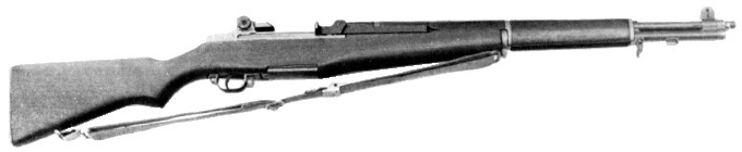
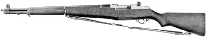
The Ml Garand is an air-cooled, gas-operated, clip-fed, semiautomatic, .30 caliber shoulder weapon. This means that:
- air cools the barrel
- the power to cock the rifle and chamber the succeeding round comes from the expanding gas of the round fired previously
- the rifle is loaded by inserting a metal clip (containing a maximum of eight rounds) into the receiver
- the rifle fires one round each time the trigger is pulled
The M1 was replaced by the M14 rifle in U.S. service.
The trigger must be pulled to fire each round. When the last round is fired, the empty clip is
automatically ejected and the bolt remains to the rear.
Each time a round is loaded and fired, many parts inside the rifle work in a given order. This
is known as the cycle of operation. The M1 cycle of operation is broken down into eight steps.
Assume that a full or partially filled clip has been loaded into the rifle and that the first round has been fired
and the bolt is in its rearmost position (figure 1).
- Feeding:
Feeding takes place. when a round is moved into the path of the bolt. This is done by the
follower assembly exerting an upward pressure on the bottom round in the clip. The follower assembly is continuously
forced up by the pressure of the operating rod spring through the follower rod and follower arm (figure 1).
- Chambering:
Chambering occurs when a round is moved into the chamber. This takes place as the bolt goes
forward under pressure of the expanding operating rod spring, picking up the top round in the clip and driving it
forward into the chamber (figure 2). Chambering is complete when the extractor snaps into the extracting groove on
the cartridge case and the ejector is forced into the face of the bolt.
- Locking:
Locking is complete when the bolt is fully closed. This prevents the loss of gas pressure until the
bullet has left the muzzle. The bolt is locked by the rear camming surface in the recess in the hump of the
operating rod, forcing the operating lug of the bolt down. This engages the locking lugs on the bolt with their
recesses in the receiver (figure 3).
- Firing:
Firing occurs when the firing pin strikes the primer. As the trigger is pulled the trigger lugs are
disengaged from the hammer hooks and the hammer is released. The hammer moves forward under the pressure of the
hammer spring and strikes the tang of the firing pin, driving the firing pin against the primer and firing the round (figure 4).
- Unlocking:

Unlocking occurs after the firing of the round. As the bullet is forced through the barrel by the
expanding gas, a small portion of the gas escapes through the gas port into the gas cylinder, forcing the operating
rod to the rear (figure 5a). The camming surface inside the recess in the hump of the operating rod forces the
operating lug of the bolt upward, disengaging the locking lugs from their recesses in the receiver. The bolt is
thus unlocked and ready to be moved to the rear (figure 5b).
- Extracting:
Extracting is pulling the empty cartridge case from the chamber. The extractor, which is engaged
with the extracting groove on the cartridge case, withdraws the empty case as the bolt moves to the rear (figure 6).
- Ejecting: Ejecting is throwing the empty case from the rifle. As the bolt moves to the rear, withdrawing the
case from the chamber, the round is held in place by the chamber walls. When the mouth of the empty case clears the
chamber, it is ejected up and to the right by the expanding ejector spring and ejector.
- Cocking:
Cocking occurs when the hammer is forced into the proper position for firing the next round. This
happens as the bolt continues to the rear. The rear end of the bolt forces the hammer back and rides over it. The
hammer is caught by the sear if the trigger is still held to the rear, but it is caught by the trigger lugs if
trigger pressure has been released (figure 7).
The M1, M1C, and M1D rifles are basically the same mechanically, as well as in operation and functioning.
- M1
-
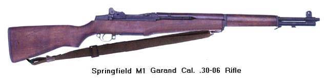
1936. "Rifle, Caliber .30, M1". Original production model.
- M1C
-
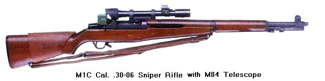
"Rifle, Caliber .30, M1C (Sniper's)". A standard M1 rifle with a telescope mounted to the
receiver and a cheek pad laced to the stock. The barrel can be equipped with a flash hider.
- M1D
-
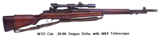
"Rifle, Caliber .30, M1D (Sniper's)". Differs from the M1C only in the design of the telescope
mount and bracket, which is attached to the barrel.