| TECHNICAL DATA |
|---|
| | M3, M3A1 |
|---|
| Alternative Designations | "Grease Gun" |
|---|
| Country of Origin | USA |
|---|
| Date Of Introduction | M3: 1942. M3A1: 1944 |
|---|
| Caliber | 0.45 in (11.43 mm) |
|---|
| Cartridge | .45 ACP - Automatic Colt Pistol |
|---|
| System of Operation | Blowback |
|---|
| Weight With No Magazine | M3: 8.0 lb (3.6 kg). M3A1: 7.8 lb (3.5 kg) |
|---|
| Length | Stock Extended: 29.8 in (757 mm)
Stock Forward: 22.8 in (579 mm) |
|---|
| Barrel Length | 8.0 in (203 mm) |
|---|
| Barrel Rifling | R.H., four lands, pitch 1 in 16 inches (406 mm) |
|---|
| Safety Features | Closed receiver cover prevents firing of weapon. No mechanical means of locking the trigger. |
|---|
| Trigger Pull | 4.5 to 7.5 lb (2 to 3.4 kg) |
|---|
| Magazine Capacity | 30 rounds |
|---|
| Weight of Empty Magazine | 0.75 lb (0.34 kg) |
|---|
| Weight of Full Magazine | 2.10 lb (0.95 kg) |
|---|
| Performance |
|---|
| Rate of Fire | 350 to 460 rds/min
Sustained: 40 to 60 rds/min |
|---|
Muzzle Velocity
(Ball, 234 grain bullet) | 920 fps (280 mps) |
|---|
| Muzzle Energy | 440 foot-pounds (596 J) |
|---|
Maximum Range
(Ball, 30° elevation) | 760 yd (695 m) |
|---|
| Sights |
|---|
| Sight Radius | 10.9 in (276 mm) |
|---|
DESCRIPTION
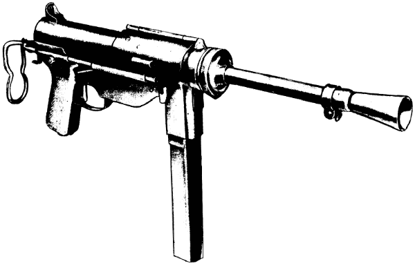
The M3 and M3A1 submachine guns are air-cooled, blowback-operated, magazine-fed, automatic shoulder weapons. They are light, compact
and rugged. The stock is one piece of formed steel rod which can be telescoped for ease of handling and the ends are drilled and
tapped for usage as a cleaning rod. The stock can also be used as a disassembly tool or wrench and is made so it can be utilized to
load the magazine.
There is no provision for semi-automatic fire, however, because of the low cyclic rate of fire the operator can fire single shots
through trigger manipulation.
Both submachine guns are fed a magazine which has a capacity of 30 rounds.
For convenience of maintenance, the weapons are divided into groups and assemblies which consist of magazine, barrel, gun stock
extension. bolt and guide rod group, trigger housing group, trigger and sear group, and receiver assembly.
Following World War II, a curved barrel was made for use with the M3A1. The M9 flash hider was developed for use with both the M3 and M3A1.
Replaced by the M4 Carbine and MP5 submachine gun in U.S. service.
VARIANTS
- M3 (NSN 1005-672-1767)
-
1942. Original production model. The M3 was designed specifically to simplify production by making use of stamped metal parts.
A number of deficiencies were found during the initial two years of use. These deficiencies were corrected in the M3A1 model.
- M3A1 (NSN 1005-672-1771)
-
 1944. The M3A1 was used during World War II and Korea. Basically the same as the M3 with the following differences:
- The M3A1 housing assembly has been changed in design to eliminate the retracting handle, spring, lever assembly, and oiler clip.
It contains the ejector, which is secured to the housing by two rivets.
- The bolts for the M3 and M3A1 vary in design. The M3A1 bolt contains a circular cut which permits the cocking of the weapon by
retracting the bolt with the finger. It also contains an ejector groove extending the length of the bolt. This permits the removal
of the bolt and guide rod group without necessitating the removal of the trigger guard and housing assembly from the weapon. The
retracting lever pawl notch has been eliminated and a coverhinge-rivet clearance slot has been added.
- The M3A1 receiver assembly is designed to incorporate the oiler in the stock. The cover hinge is riveted and
now is part of the receiver body.
- The M3A1 was also designed so it could fire 9mm Parabellum cartridges by changing the barrel and bolt and adding an adapter to
the magazine.
OPERATION
The gun has no mechanism for semiautomatic fire. However, it is possible to fire single shots by proper manipulation
of the trigger, pressing it and then quickly releasing it. It takes practice for a firer to become proficient at firing single shots.
When firing long bursts, the weapon has a tendency to move up and to the right. The firer can control this tendency
by always taking a correct firing position.
When the magazine has been emptied, the bolt will close on the empty chamber. Cock and lock the weapon before
inserting another loaded magazine.
Safety cannot be overemphasized. The M3 and M3A1 submachine gun have no mechanical means of locking the trigger. The
insertion of a loaded magazine loads the gun. If the cover is open and the bolt cocked, pressure on the trigger will
fire the gun. If an unlocked gun is dropped, it may fire whether the bolt is cocked or not.
Each time a cartridge is fired, the parts inside the submachine gun function in a given order.
This is known as the cycle of operation.
Note that in the submachine gun, the chamber pressure is relatively low and the bolt is relatively heavy; this eliminates the need for the steps of locking and unlocking.
- Feeding:
- When a loaded magazine is placed in the weapon, the magazine catch holds the magazine in position.
The top cartridge is held against the lips of the magazine through the action of the magazine spring and follower.
When the bolt moves forward, it removes the round from the magazine.
- When the bolt moves to the rear and clears the top of the magazine, the next cartridge is placed against the lips of the magazine by the action of the magazine spring and follower.
- Chambering: The bolt, moving forward under the action of the expanding driving springs, pushes the top cartridge out of the magazine.
The lips of the magazine aid to aline the cartridge with the chamber.
As the bolt continues forward, the cartridge is pushed into the chamber by the front of the bolt and the extractor.
The base of the cartridge protrudes slightly from the chamber when the cartridge is fully seated.
- Firing: After the cartridge is chambered, the bolt continues to move forward.
The extractor springs out to the side and snaps into the extracting groove of the cartridge.
At the same time, the fixed firing pin in the center of the cartridge recess of the bolt strikes the primer of the cartridge, firing the cartridge.
At the instant of firing, the cartridge is inclosed in the chamber by the cartridge recess of the bolt, and the rim of the cartridge is engaged by the extractor.
- Extracting:
- When the cartridge is fired, the gas pressure forces the bullet out of the muzzle and the empty cartridge case out of the chamber, pushing the bolt to the rear.
The extractor holds the base of the cartridge case against the bolt.
The bolt continues moving to the rear, carrying the empty cartridge case with it.
Extraction is completed when the front of the cartridge case clears the rear of the chamber.
- If the cartridge is not fired, the extractor will remove it from the chamber when the bolt is manually pulled to the rear.
- Ejecting: As the bolt moves to the rear, the empty cartridge case is held by the extractor.
The base of the cartridge strikes the fixed ejector.
The extractor serves as a pivot point for the cartridge, which is deflected out of the ejection opening of the receiver.
The extractor and ejector are both needed to complete the ejection.
- Cocking: As the bolt moves to the rear, the driving springs are compressed.
If the trigger has been released, the nose of the sear will move up.
As the bolt moves forward, the sear nose will engage in the sear notch and hold the bolt to the rear in a cocked position.
If the trigger has not been released, the bolt will continue forward and the cycle of operation will be repeated.
Caution. If the gun is accidentally dropped, the bolt may be jarred far enough to the rear to clear the top cartridge in the magazine, but not far enough for the sear nose to engage in the sear notch.
When this happens, the bolt will chamber and fire the cartridge as it goes forward.
AMMUNITION
Ammunition for the M3 is issued in the form of a complete .45 ACP round. A complete round (cartridge) consists of all the components
(cartridge case, bullet, propellant powder, and primer) necessary to fire the weapon once.
Click here for more information.
- .45 M9 Blank
- .45 M26 Tracer
- .45 M1911 Ball
- .45 M1921 Dummy
- .45 M1931 Dummy
- .45 XM261 High Density Shot
More M3 Art

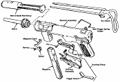
M3 major groups, assemblies, and components.
Click on image to see full size: 790x545, 36K, GIF

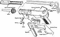
M3A1 major groups, assemblies, and components.
Click on image to see full size: 790x490, 39K, GIF


 1944. The M3A1 was used during World War II and Korea. Basically the same as the M3 with the following differences: